From everyday servicing to complex equipment faults, DentalMed provides diagnosis and specialist repair support for dental practices, laboratories and medical facilities. Explore the equipment, the problem and the work behind each repair.
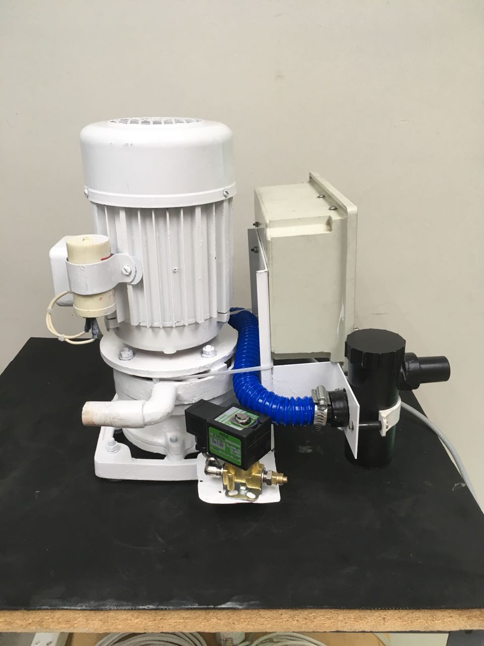
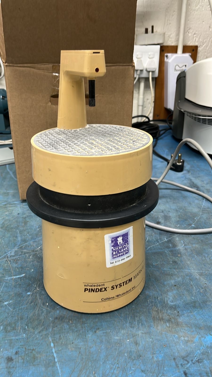
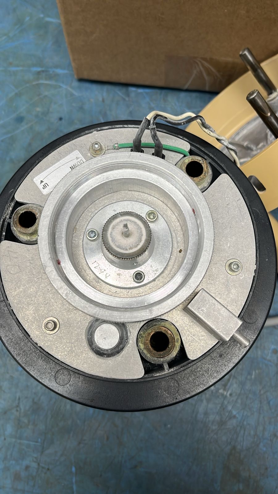
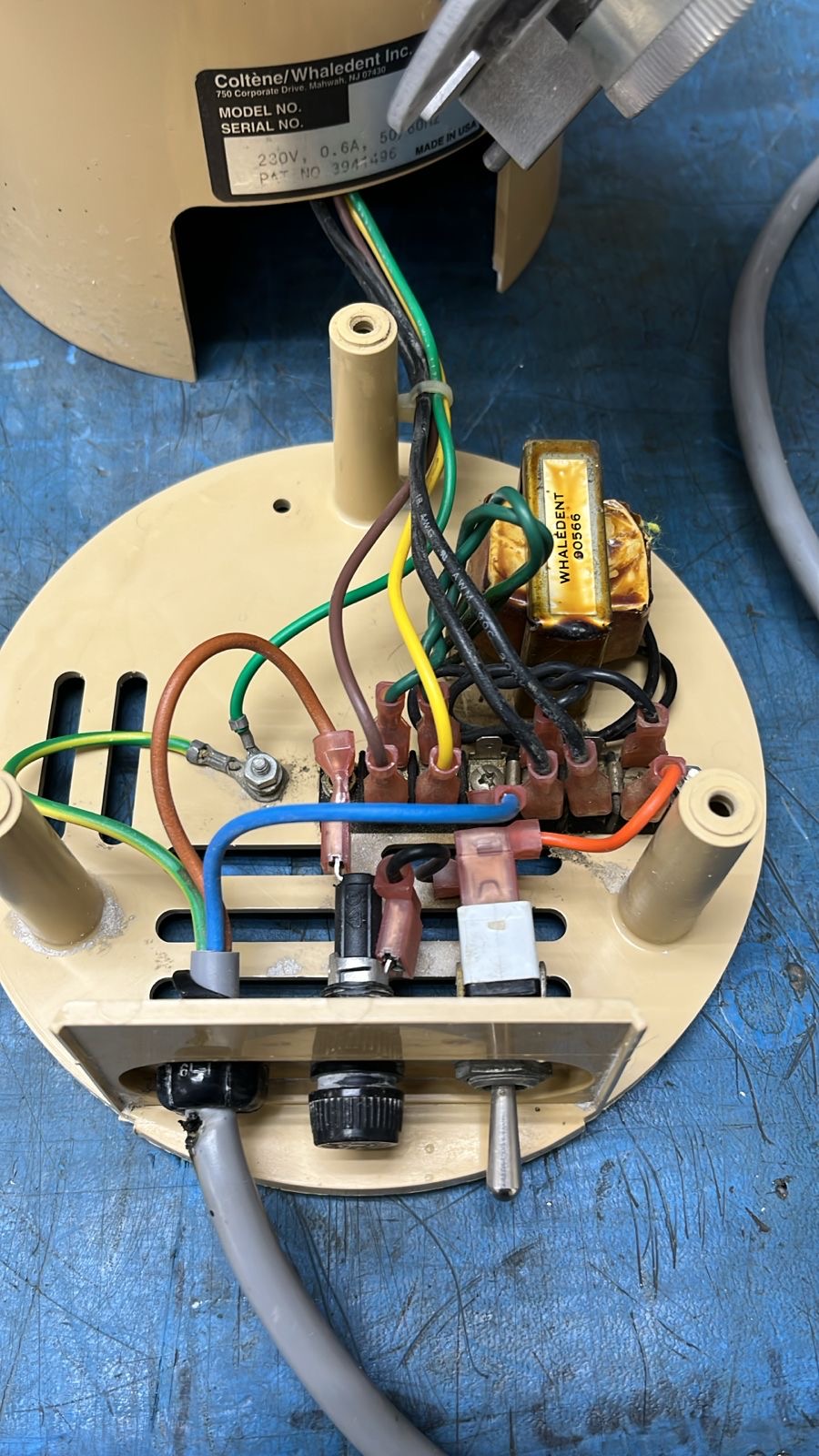
This photographic journey documents a Pindex machine in DentalMed’s workshop. The views move from the equipment exterior and identification plate to the opened housing, internal assembly and wiring.
The unit
The supplied workshop message identifies this equipment as a Pindex machine. Exterior photographs establish the unit before looking inside its housing.
Inside the workshop
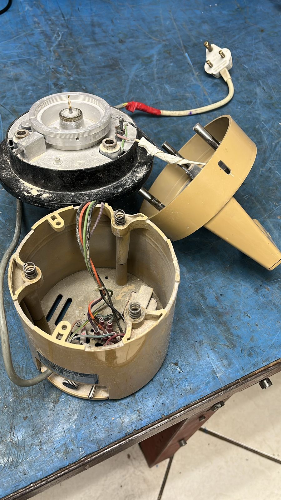
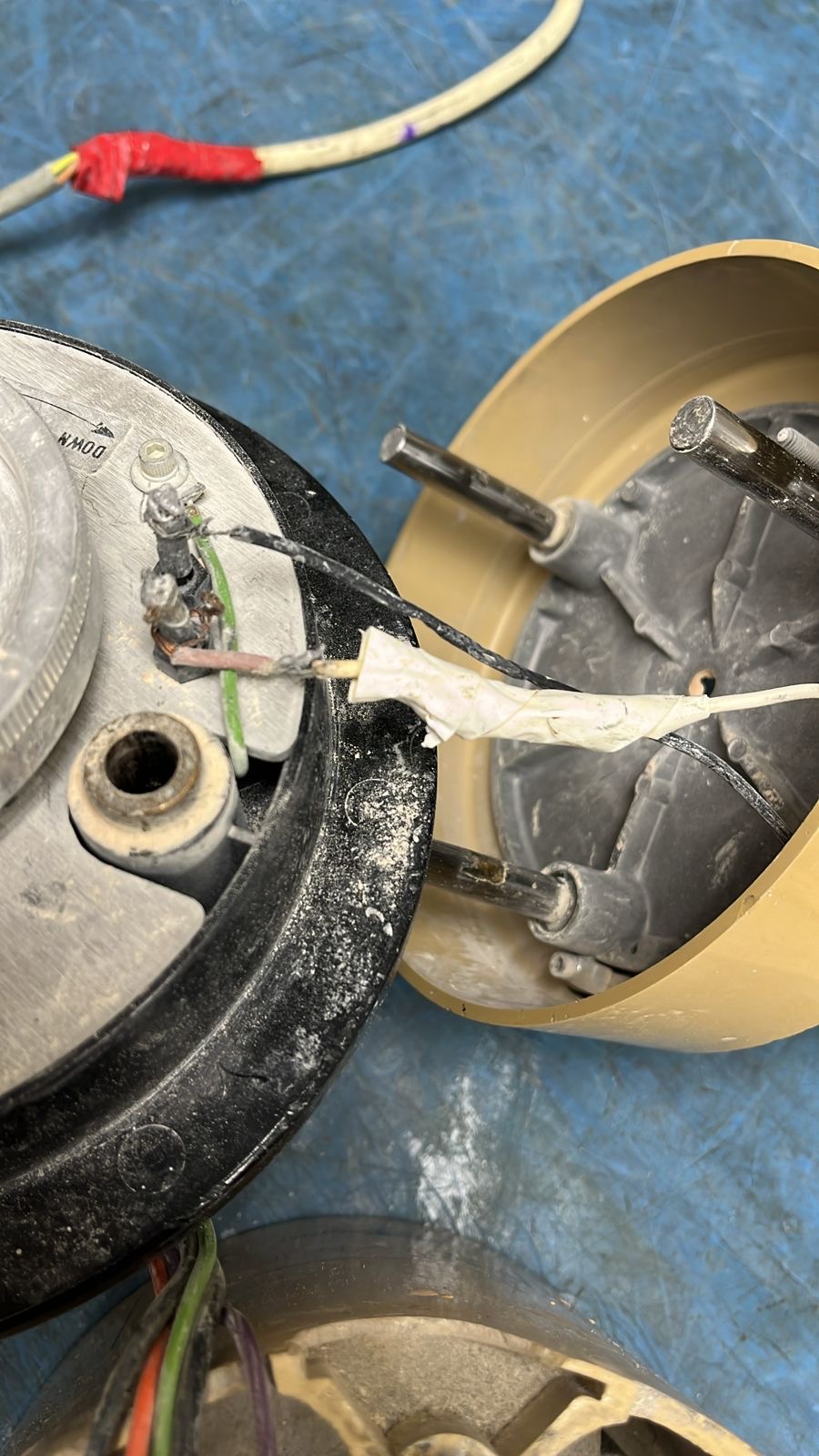
The opened views document the internal components and connections. Each photograph offers a closer look at the equipment involved in this specialist workshop job.
WORKSHOP PHOTO 1The Pindex machine on the workshop bench.WORKSHOP PHOTO 2Pindex-branded equipment casing.WORKSHOP PHOTO 3Equipment identification plate and connections.WORKSHOP PHOTO 4Opened housing with internal components exposed.WORKSHOP PHOTO 5Closer view of the separated housing and internal connections.WORKSHOP PHOTO 6Internal circular assembly viewed from above.WORKSHOP PHOTO 7Internal wiring and components during workshop inspection.
Need assistance with specialist laboratory equipment? Send DentalMed the equipment details and reported fault to discuss an assessment.
Discuss your equipment repairSteamer Heating-Element RepairWorn element replaced. Indicator light renewed.View repair journey →
Repair journey / Steamer heating element
From a worn heating element to a repaired steamer.
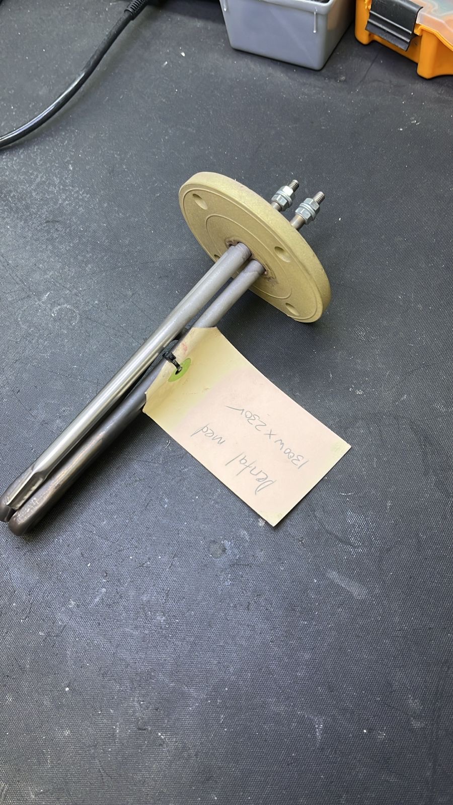
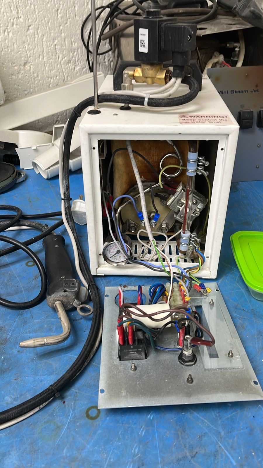
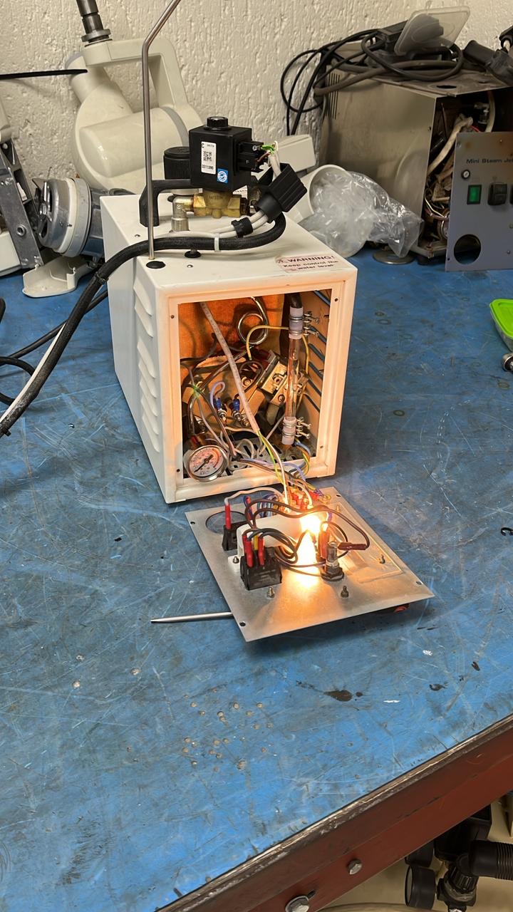
This steamer’s workshop journey shows the unit opened up, the condition of its old heating element and the new replacement. The workshop notes confirm that the unit was repaired and a light was also replaced.
What arrived
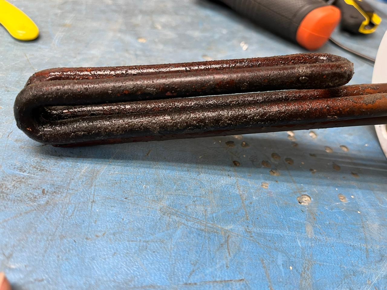
The workshop describes the old element as heavily used, with lime and rust deposits attributed to metals in the water. Close-up photographs document the element’s condition.
What changed
A new heating element was fitted and a light was replaced. The workshop reports the steamer repaired; this story follows the supplied photographs without claiming unrecorded test results.
WORKSHOP PHOTO 1The steamer opened for inspection.WORKSHOP PHOTO 2Internal components and pipework as documented on arrival.WORKSHOP PHOTO 3The removed heating element.WORKSHOP PHOTO 4Close-up of the worn element and its deposits.WORKSHOP PHOTO 5The new replacement heating element.WORKSHOP PHOTO 6The unit during the repair sequence.WORKSHOP PHOTO 7A further workshop view of the steamer.
Steamer not heating as expected? Send DentalMed the equipment details and symptoms to discuss an assessment.
Discuss a steamer repairSintering Furnace Fault DiagnosisA failed start traced to a faulty Type B thermocouple.View repair journey →
Repair journey / Sintering furnace
A furnace that would not start. A specialist sensor at the centre of the diagnosis.
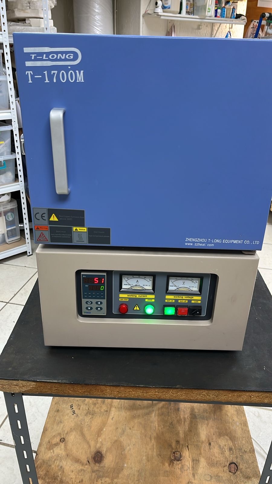
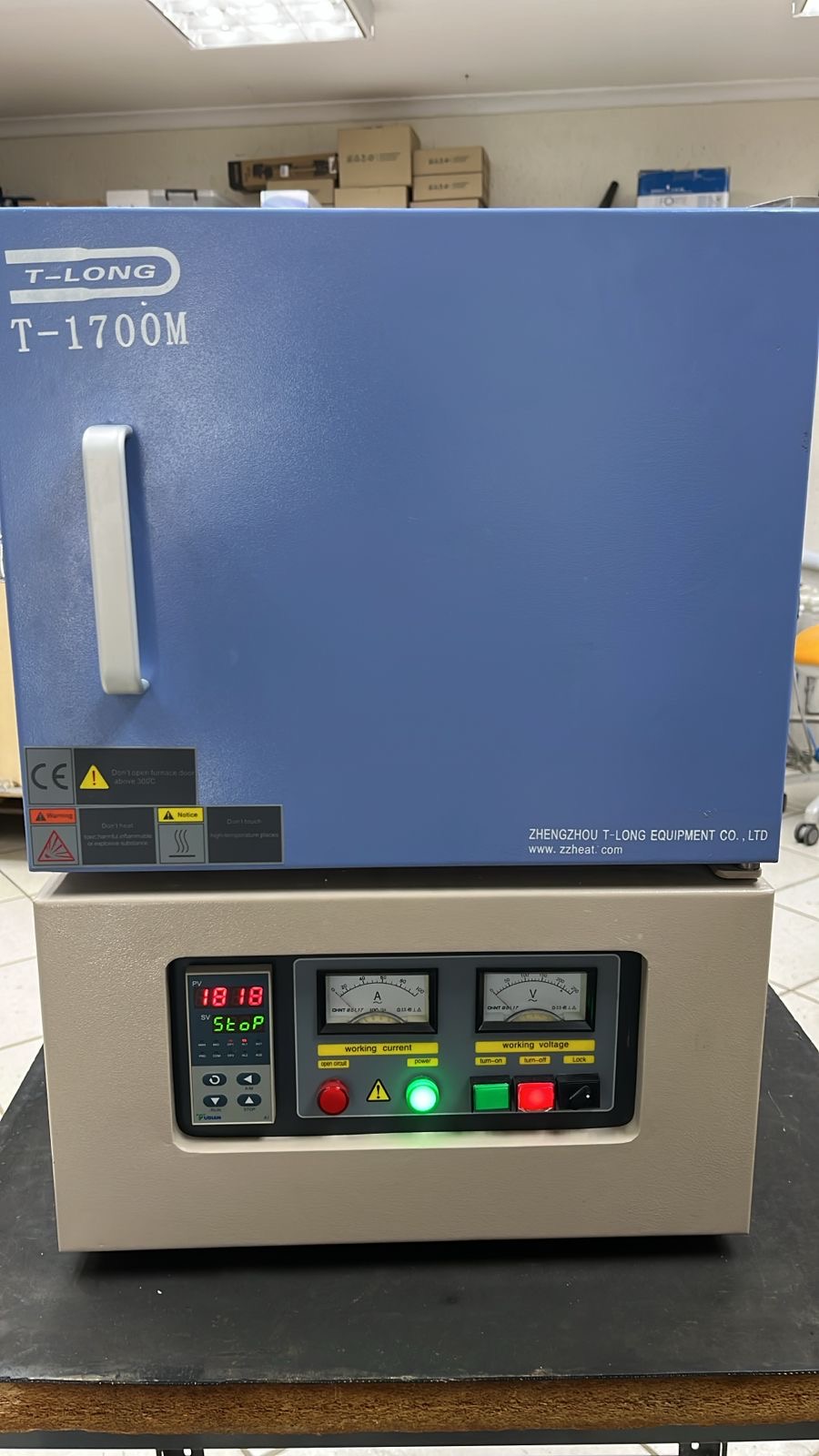
This sintering furnace arrived with a reported failure to start running. DentalMed’s workshop identified a faulty specialist thermocouple, documented in the supplied photographs and workshop notes.
The reported fault
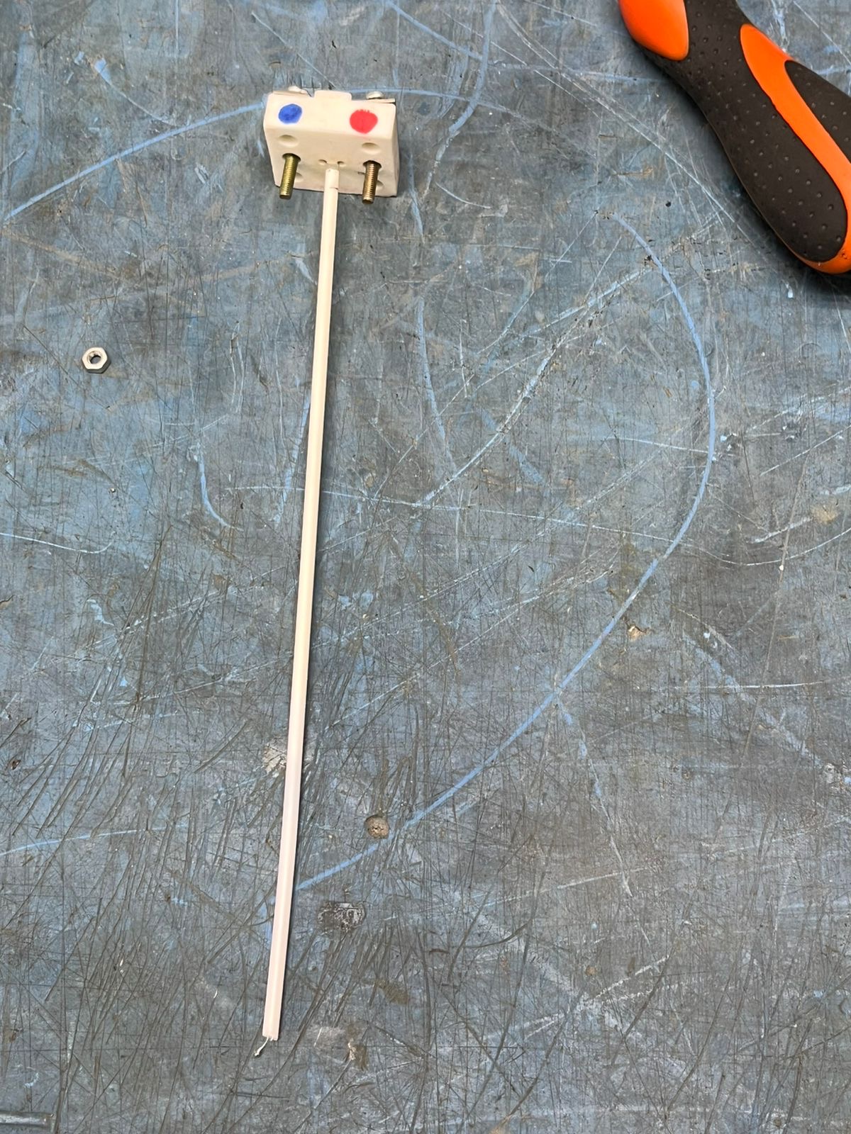
The furnace did not start its operating cycle. The workshop’s diagnosis identified the thermocouple as faulty.
The specialist component
The workshop identifies this as a Type B thermocouple used for the furnace’s high-temperature measurement requirement, stated as up to 1,800 degrees in the supplied notes.
Inside the diagnosis
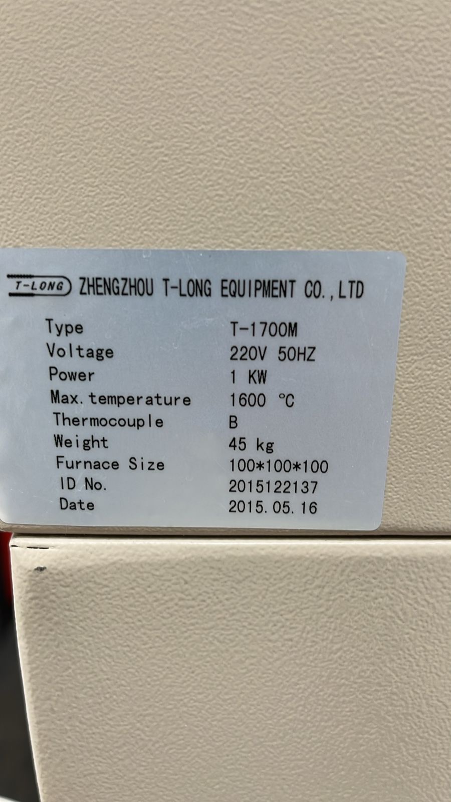
WORKSHOP PHOTO 1The sintering furnace and its front controls.WORKSHOP PHOTO 2Equipment identification label.WORKSHOP PHOTO 3The thermocouple assembly removed for inspection.WORKSHOP PHOTO 4Close-up of the thermocouple tip and ceramic sheath.WORKSHOP PHOTO 5Front view of the furnace in the workshop.WORKSHOP PHOTO 6Close-up of the furnace control panel.
Having trouble with a sintering furnace? Share the equipment details and symptoms with DentalMed to discuss specialist fault diagnosis.
Discuss a furnace repair150-Litre Oil-Free CompressorSpecialist attention to a 1,100 W compressor head.View repair journey →
Repair journey / Oil-free compressor
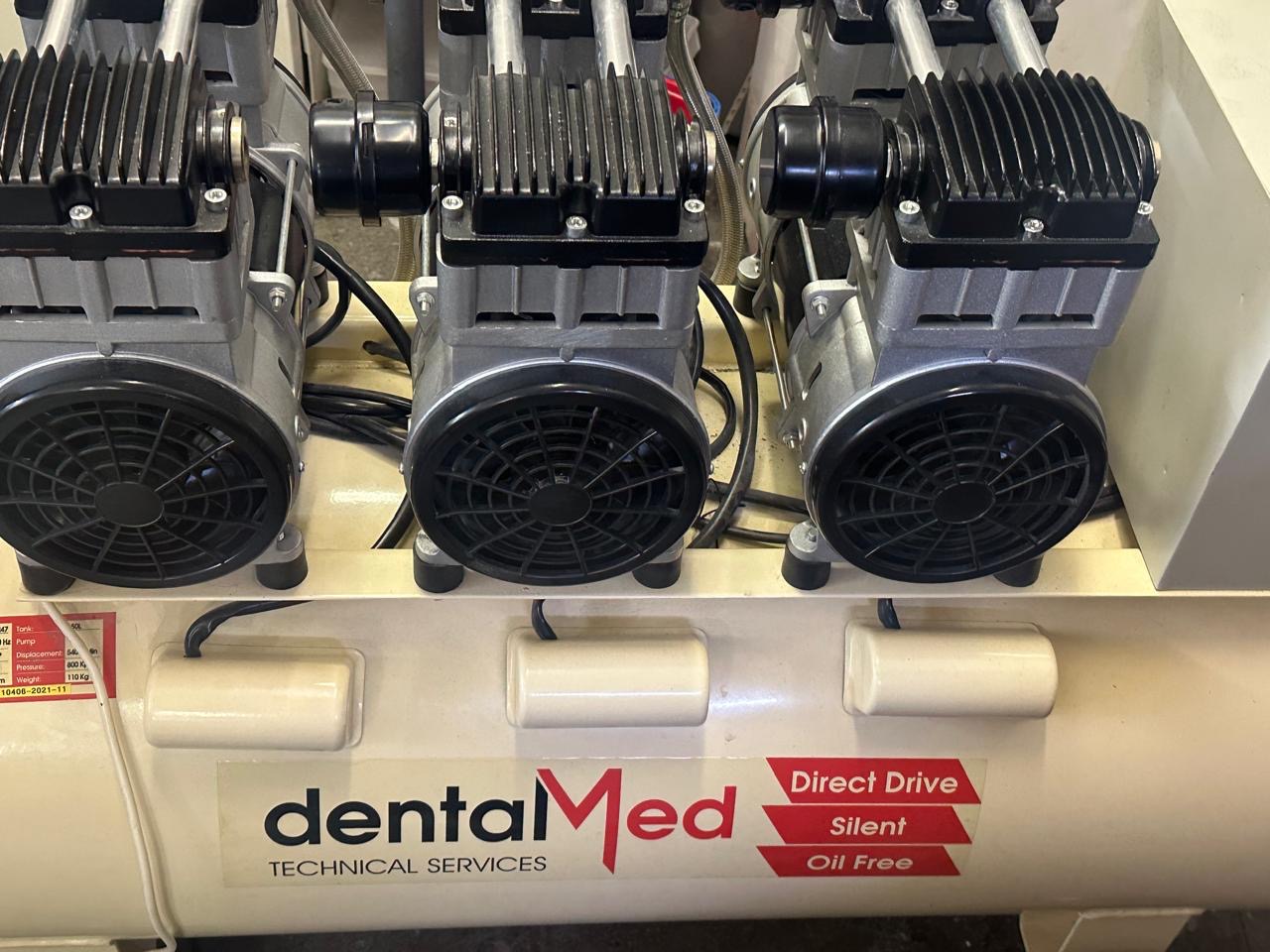
150 litres. Two compressor heads. One unit needing attention.
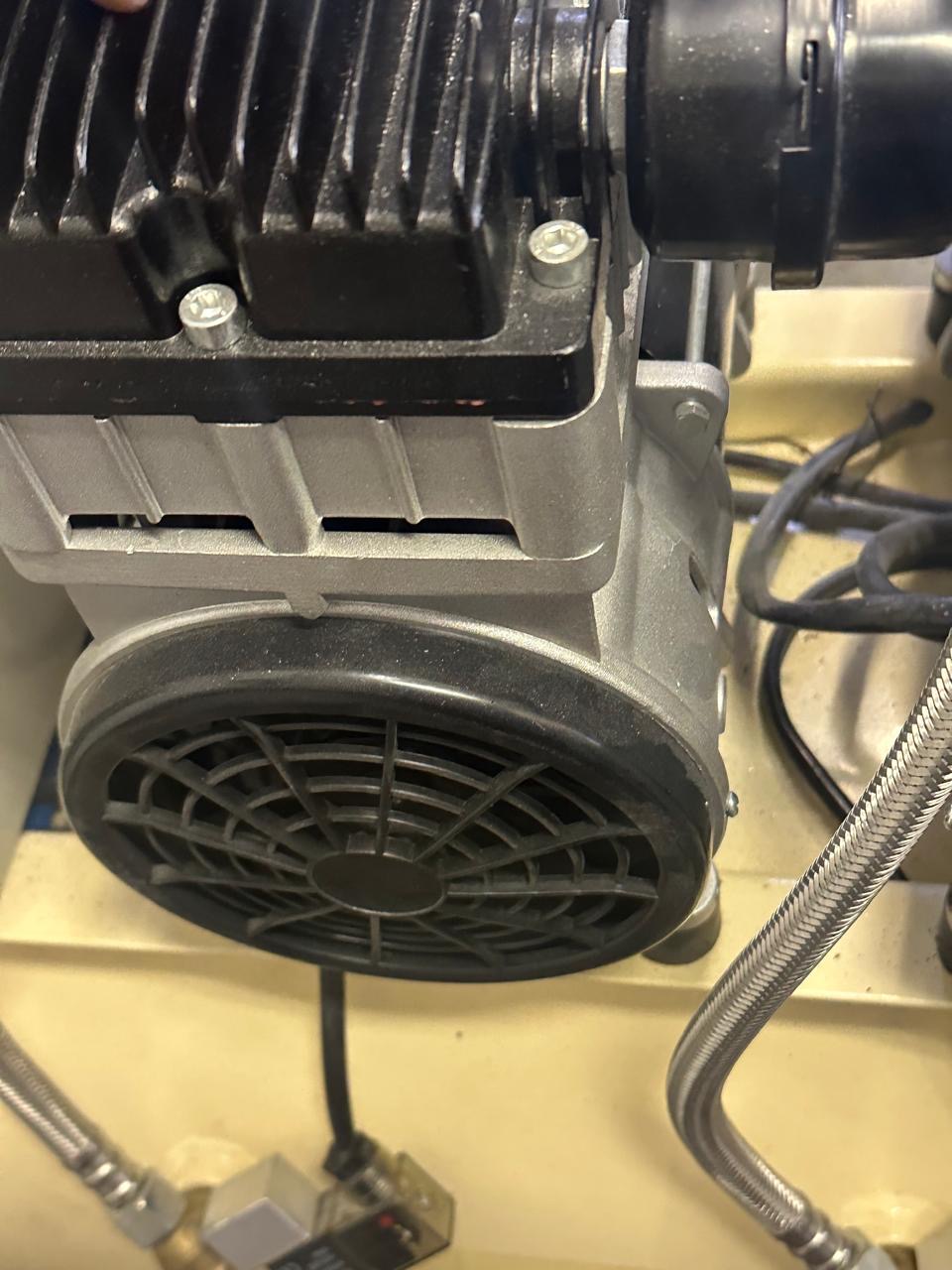
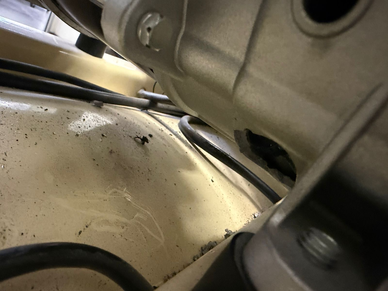
This DentalMed 150-litre oil-free compressor was brought in for attention to one of its 1,100 W compressor heads, according to the supplied workshop message. The photographs document the unit, head assemblies and receiver tank.
The equipment
A DentalMed oil-free compressor with a 150-litre receiver. The workshop photographs show the twin-head assembly and the connected components.
The reported repair requirement
The supplied message identifies one 1,100 W compressor head as the component requiring attention. These close-up views put that equipment at the centre of its own repair journey.
WORKSHOP PHOTO 1The DentalMed compressor assembly and twin heads.WORKSHOP PHOTO 2Close-up of a compressor head.WORKSHOP PHOTO 3Detail of the receiver and connected components.WORKSHOP PHOTO 4The receiver tank and equipment label.WORKSHOP PHOTO 5The compressor unit shown with protective wrapping.
Need help with a dental compressor? Send the unit details and a description of the problem to DentalMed to discuss an assessment.
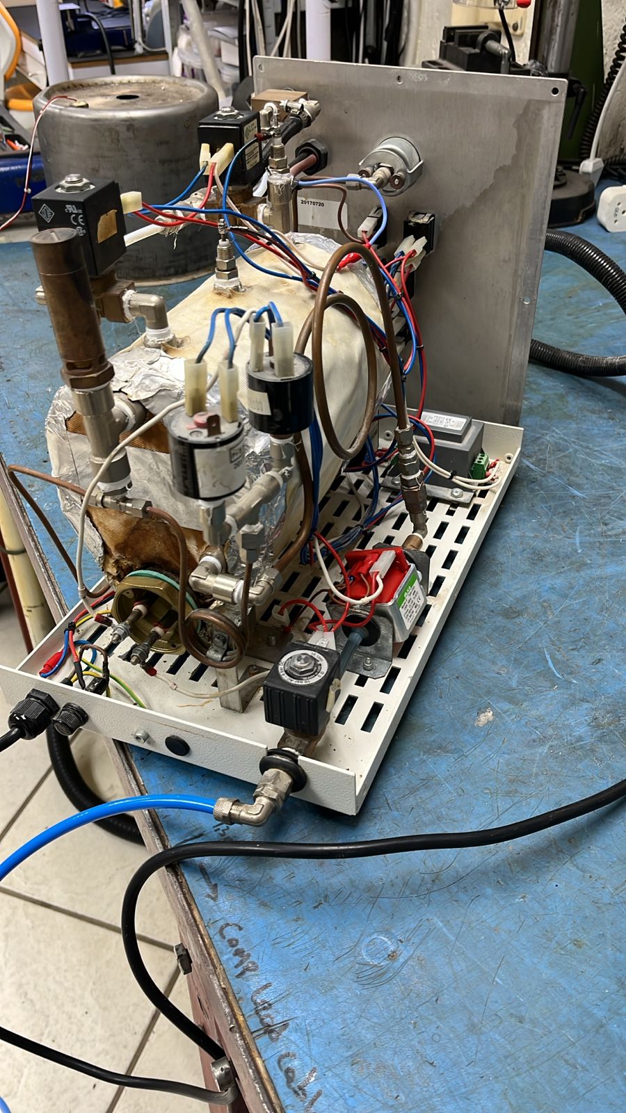
Inside a steamer: the repair story beneath the casing.
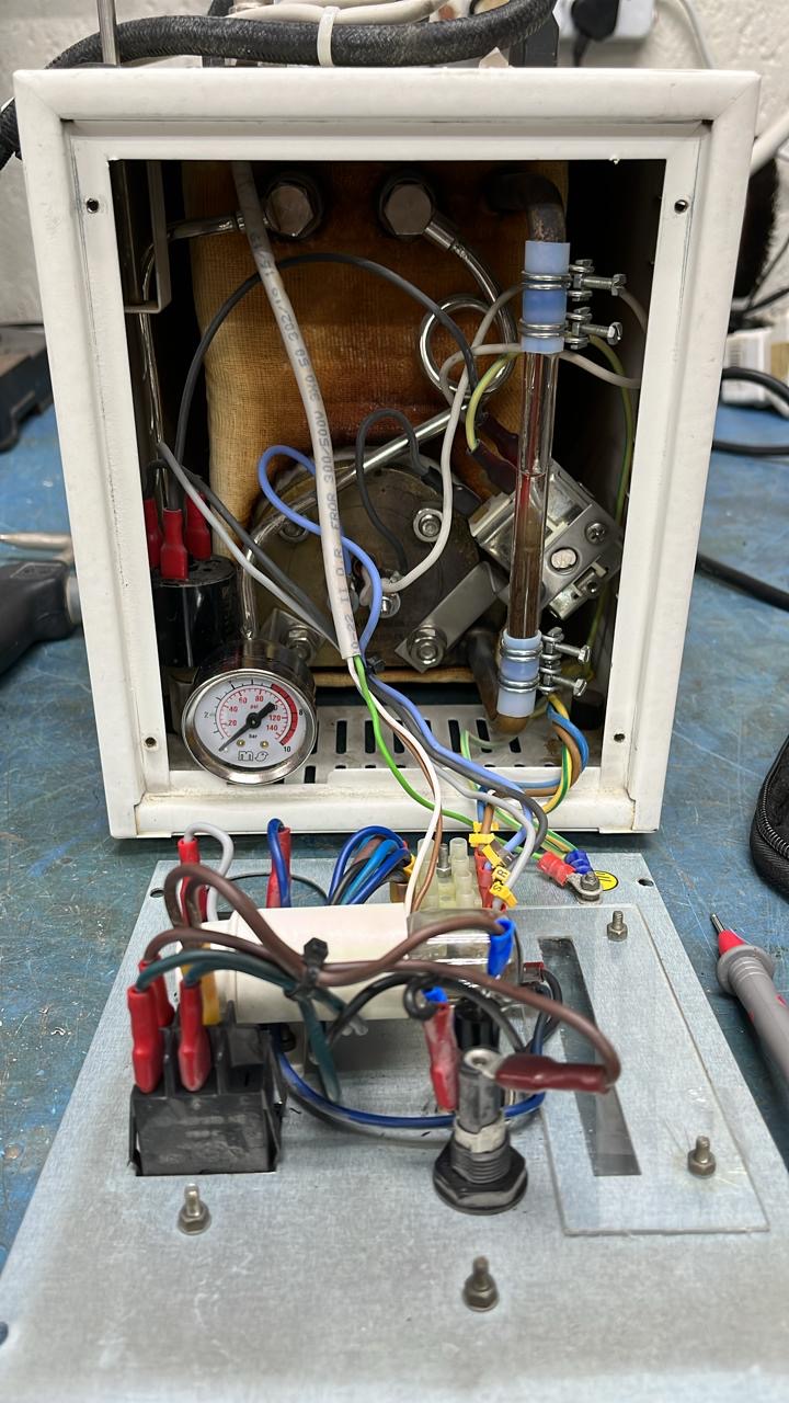
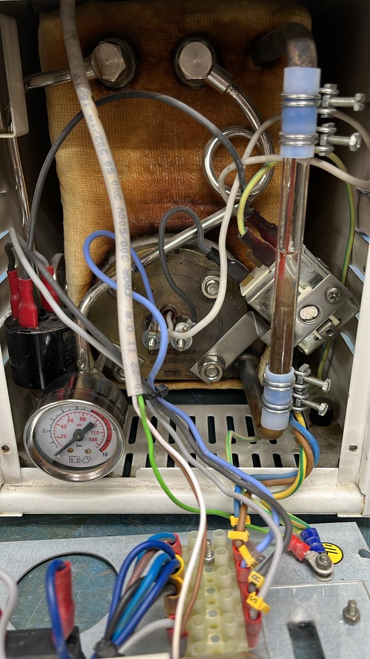
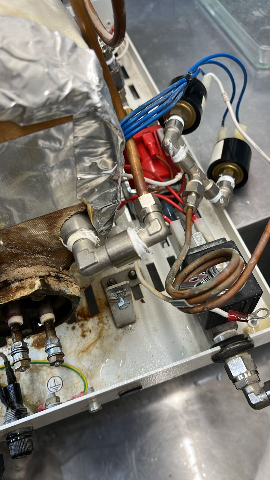
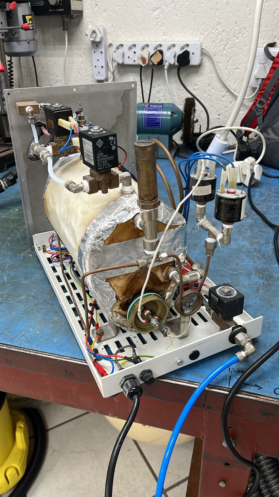
Specialist equipment work means looking beyond the exterior. This workshop sequence follows an opened steamer, its boiler connections and internal components, with a close-up of sediment removed from inside the boiler.
The equipment opened up
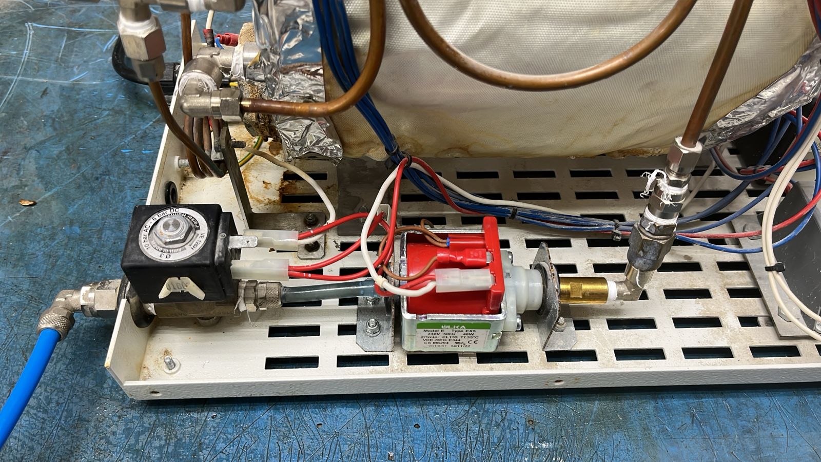
The photographs reveal the boiler, pump assembly, pipework and wiring. These detailed views make the internal workshop work visible rather than showing only the finished casing.
What the workshop documented
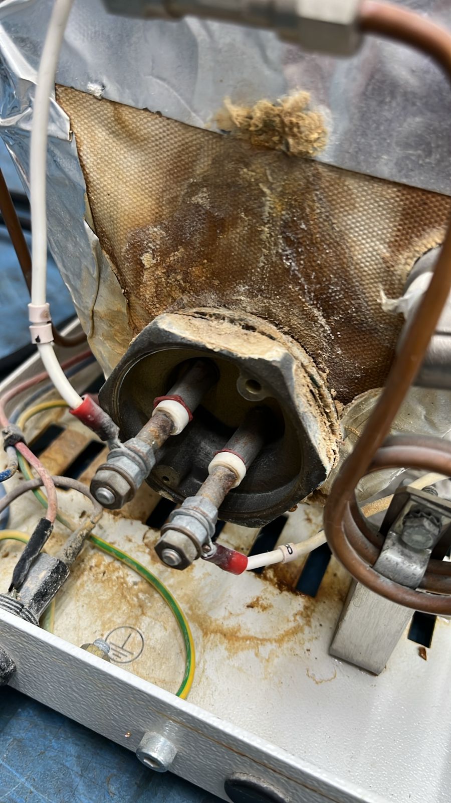
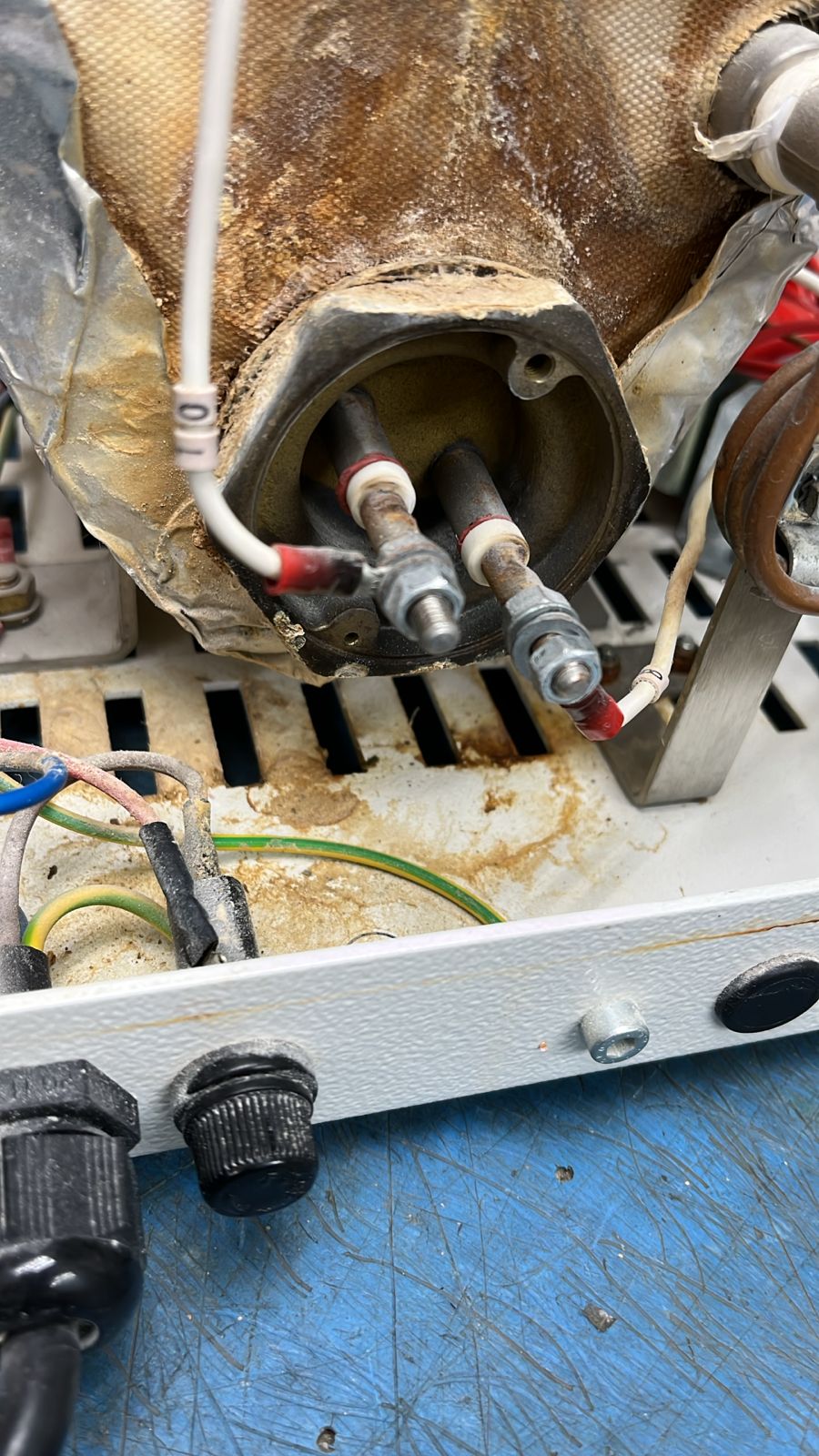
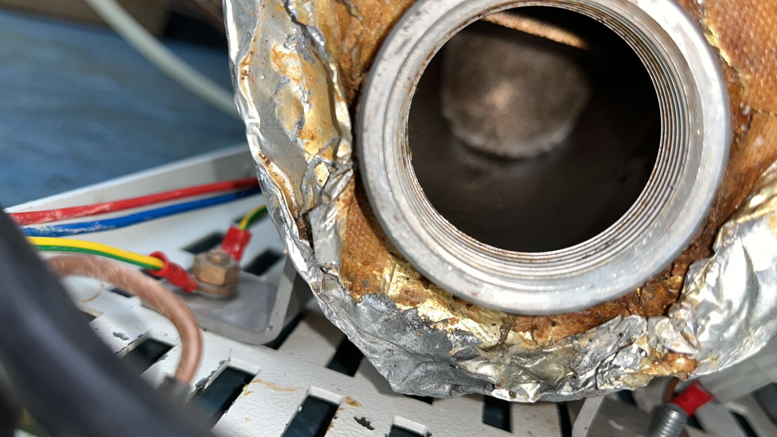
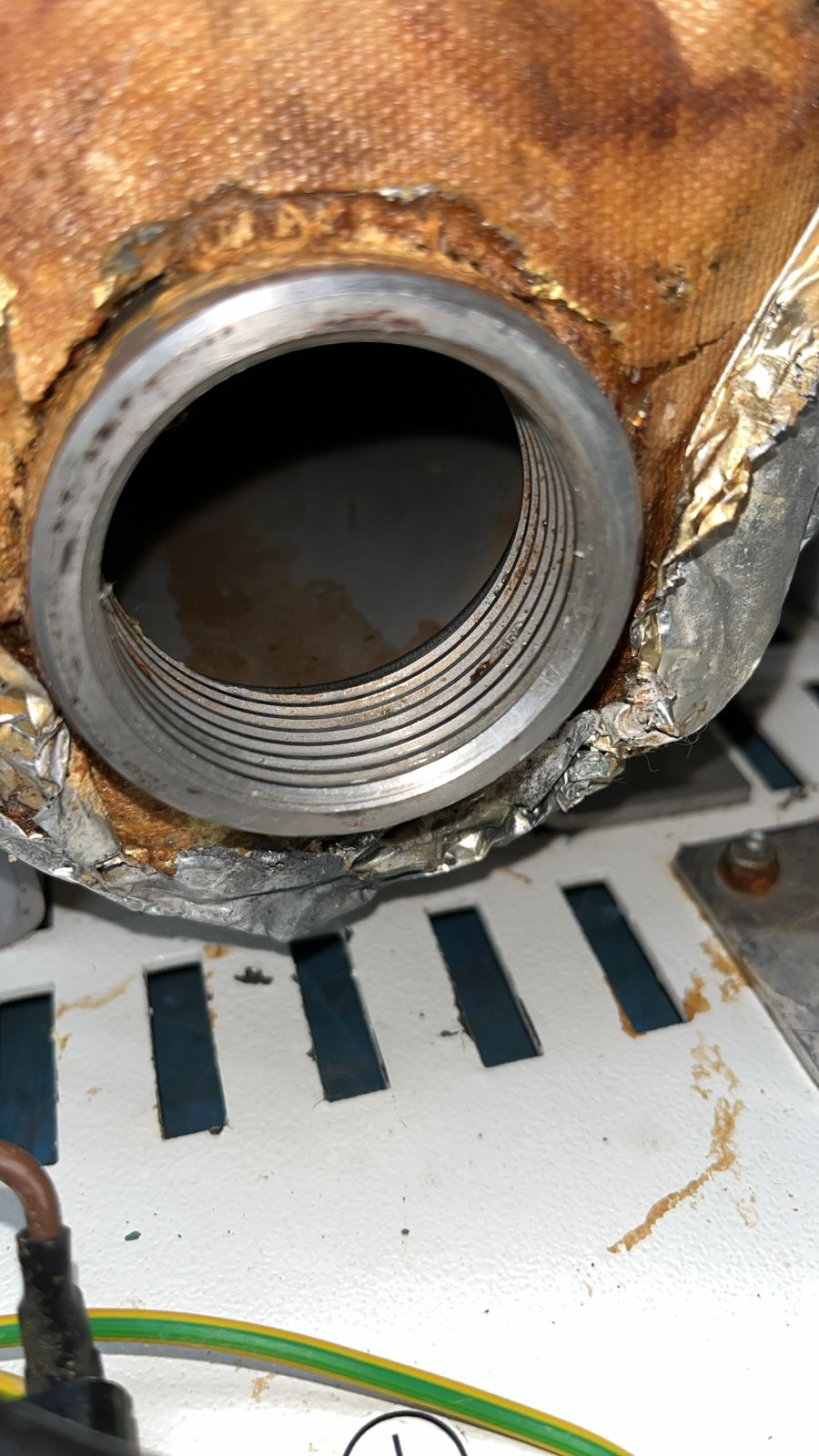
The supplied notes identify sediment coming from inside the boiler. The photographs show that material on a spoon, views through the boiler opening and the unit later enclosed and wrapped.
Follow the workshop sequence
View all 14 photographs below. Select a photograph to inspect the full image.
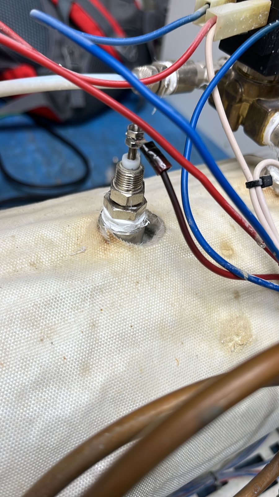
WORKSHOP PHOTO 01Pump assembly, wiring and pipework inside the opened unit.WORKSHOP PHOTO 02Close-up of a boiler-mounted connection and adjacent wiring.WORKSHOP PHOTO 03Boiler exterior and connections exposed for inspection.WORKSHOP PHOTO 04Closer inspection of the boiler opening and attached components.WORKSHOP PHOTO 05Detail of the connections beside the boiler opening.WORKSHOP PHOTO 06Pipework, valves and internal components viewed from the side.WORKSHOP PHOTO 07Sediment removed from inside the boiler, as described by the workshop.WORKSHOP PHOTO 08Close-up of the removed sediment collected on a spoon.WORKSHOP PHOTO 09View through the opened boiler connection.WORKSHOP PHOTO 10Closer view of the threaded opening and boiler interior.WORKSHOP PHOTO 11The opened unit on the workshop bench.WORKSHOP PHOTO 12Internal components and wiring during the workshop work.WORKSHOP PHOTO 13Boiler connections and internal layout from another angle.WORKSHOP PHOTO 14The enclosed unit shown wrapped after the workshop sequence.
Workshop video
Have a steamer or other specialist equipment that needs attention? Send DentalMed the equipment details and a description of the fault to discuss an assessment.